Annotating UML with Design Patterns as Visual Objects
Conventional UML has a blind spot. Once a diagram grows beyond a handful of classes, you can see all the classes and relationships perfectly well — but you have to mentally recognise that “oh, these four classes are actually an Observer pattern”. The structure is visible; the design intent is not.
This post is about an idea I prototyped years ago and keep coming back to: treating the design pattern itself as a visual object layered on top of ordinary UML.
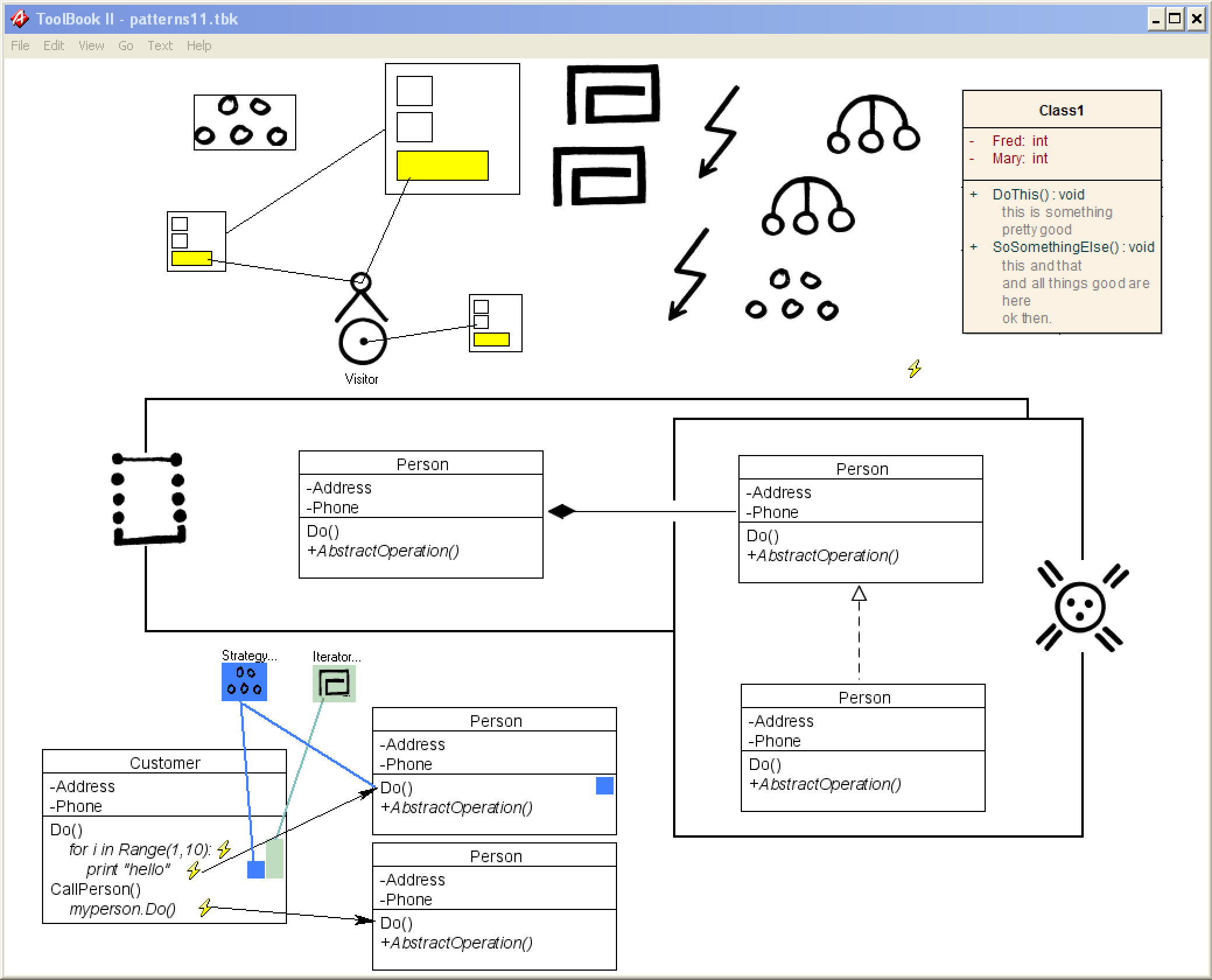 This is an example of what design patterns as visual objects might look like.
The idea
Instead of simply drawing a UML diagram of a pattern, you annotate an existing diagram with small pattern glyphs — Strategy, Iterator, Observer, and so on. Each glyph is essentially a semantic annotation, and coloured leader lines say: “these particular UML elements collectively constitute this pattern.”
             [ Strategy ]
             /    |     \
            /     |      \
       Context   Strategy  ConcreteStrategy
          |          |          |
        Do()  --->  operation() <---
The important property is that the underlying UML doesn’t have to be distorted to accommodate the annotation. The pattern layer floats above the ordinary diagram.
Leader lines that point at anything
Here’s the aspect of this notation I like most — the one that makes it more than “just put an icon next to a diagram”:
The pattern’s leader lines don’t necessarily point only at classes. They can point at a method, a relationship, or even a particular piece of code/behaviour.
This matters because patterns aren’t merely sets of classes. A Strategy isn’t just “Customer has a Strategy class”; it’s about the relationship between the context, the strategy abstraction, the concrete strategies, and the operation through which the strategy gets invoked. Look at the ASCII diagram above: the glyph’s lines attach to Do(), to operation(), to the inheritance of ConcreteStrategy — to the whole web of participants, not just the boxes.
Conventional pattern diagrams lose exactly this. They draw the classes, and leave you to infer which method call or which relationship is the heart of the pattern. When your annotation can attach to the invocation itself — the arrow, the method, the behaviour — the diagram finally says what the pattern actually is, not just where its classes happen to sit.
That’s much closer to how patterns actually work, and to how the GOF catalogue describes them: as collaborations between participants playing roles, not as blobs of classes.
Why this works
Beyond the leader lines, one more aspect of this notation gives it its power:
Recognition shouldn’t be the reader’s job. In a large diagram, the hardest part of understanding it is pattern recognition — spotting which collection of elements forms a Factory Method, which trio forms a Bridge. Making patterns explicit as first-class visual objects removes that cognitive burden from every reader of the diagram.
What a tool could do with this
I can imagine this becoming a surprisingly elegant feature in my own UML tools — GitUML (my flagship diagramming tool, which already uses AI to generate code explanations that interleave prose and UML diagrams) or Pynsource, my UML tool for Python:
- You draw ordinary UML.
- You select some elements and attach a
<<Strategy>>,<<Observer>>,<<Factory Method>>etc. annotation. - The tool renders the pattern as a small distinctive glyph, and draws unobtrusive “pattern scope” connectors to its participants.
And there’s an interesting consequence: patterns could become navigable objects rather than merely decorations. Click the Strategy glyph and the tool could:
- highlight all participating classes, methods and relationships,
- show the canonical pattern structure alongside your actual implementation,
- tell you which participants are missing or don’t conform to the usual structure.
The old prototype I built (in ToolBook, of all things) was primitive — ToolBook was primitive — but the underlying concept is considerably more sophisticated than “put an icon next to a UML diagram”. It’s a good conceptual prototype of a real diagramming feature.
Going in reverse
The really interesting bit: this could work in reverse too. Detect patterns from the code or UML and add the glyphs automatically. Then the diagram becomes not just a representation of structure, but a representation of the design intent that emerges from that structure.
That flips the usual relationship between patterns and diagrams. Instead of a pattern being something you hand-draw into a diagram, the diagram becomes a view onto the patterns that already live in your codebase — and the annotation layer becomes a lens on architectural intent.
This is the direction my GitUML project is heading: point it at a GitHub repository and it renders the structure as browsable UML, with AI-driven code explanations generating prose and diagrams interspersed. Pattern glyphs like these would be a natural next layer — diagrams that show not just structure, but design intent.
Another example
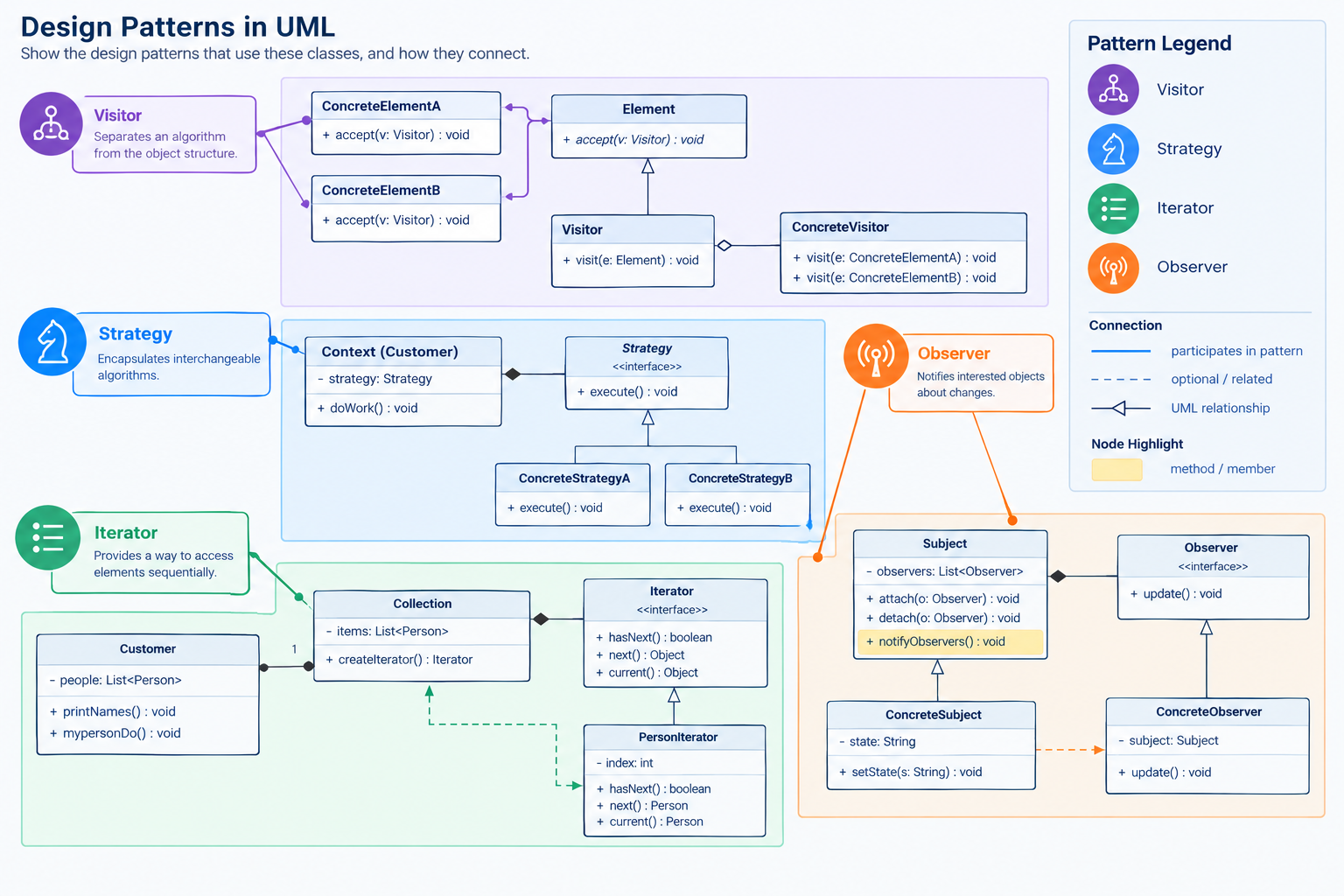 Another example of what design patterns as visual objects might look like.
Where this fits
This sits alongside my earlier thoughts on pattern automation and the central patterns repository. The common thread: patterns as machine-readable, tool-addressable entities — not just prose in a catalogue. Try GitUML to see where this is going.